
safety (emergency) circuits requirements FOR PLC & HMI power supply in Malaysia
Introduction
The source for a PLC power supply is generally single-phase and 120 or 240 VAC . If the controller is installed in an enclosure, the two power leads (L1 hot and L2 common) normally enter the enclosure through the top part of the cabinet to minimize interference with other control lines.
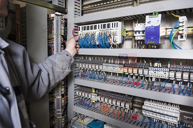
PLC power supply and safety (emergency) circuits requirements
The power line should be as clean as possible to avoid problems due to line interference in the controller and I/O system.
Power requirements
a. Common AC source
The system power supply and I/O devices should have a common AC source (see Figure 1). This minimizes line interference and prevents faulty input signals stemming from a stable AC source to the power supply and CPU, but an unstable AC source to the I/O devices.
By keeping both the power supply and the I/O devices on the same power source, the user can take full advantage of the power supply’s line monitoring feature.
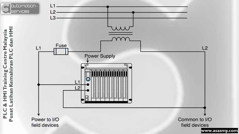
Figure 1 – System power supply and I/O devices with a common AC source
If line conditions fall below the minimum operating level, the power supply will detect the abnormal condition and signal the processor, which will stop reading input data and turn off all outputs.
b. Isolation transformers
Another good practice is to use an isolation transformer on the AC power line going to the controller.
An isolation transformer is especially desirable when heavy equipment is likely to introduce noise into the AC line . An isolation transformer can also serve as a step-down transformer to reduce the incoming line voltage to a desired level.
The transformer should have a sufficient power rating (in units of volt- amperes) to supply the load, so users should consult the manufacturer to obtain the recommended transformer rating for their particular application.
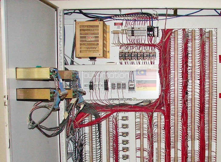
Small 120 to 120 VAC Isolation transformer in the upper left hand corner (gold box). This is also used to protect the sensitive PLC equipment as much as possible. (photo credit: lewistecheng.com)
Safety (emergency) circuits
The PLC system should contain a sufficient number of emergency circuits to either partially or totally stop the operation of the controller or the controlled machine or process (see Figure 2).
IMPORTANT! These circuits should be routed outside the controller, so that the user can manually and rapidly shut down the system in the event of total controller failure. Safety devices, like emergency pull rope switches and end-of-travel limit switches, should bypass the controller to operate motor starters, solenoids, and other devices directly.
These emergency circuits should use simple logic with a minimum number of highly reliable, preferably electromechanical, components.
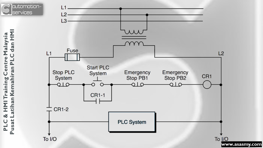
Figure 2 – Emergency circuits hardwired to the PLC system
a. Emergency stops
The system should have emergency stop circuits for every machine directly controlled by the PLC . To provide maximum safety, these circuits should not be wired to the controller, but instead should be left hardwired.
These emergency switches should be placed in locations that the operator can easily access .
Emergency stop switches are usually wired into master control relay or safety control relay circuits, which remove power from the I/O system in an emergency.
b. Master or Safety control relays
Master control relay (MCR) and safety control relay (SCR) circuits provide an easy way to remove power from the I/O system during an emergency situation (see Figure 8).
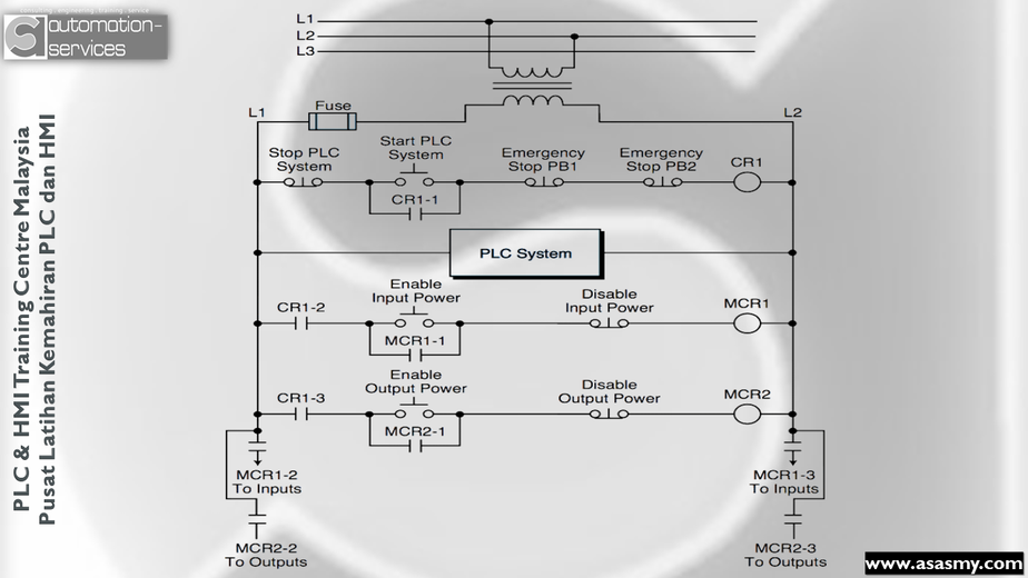
Figure 3 – Master start control for a PLC with MCRs enabling input and output power
These control relay circuits can be de-energized by pushing any emergency stop switch connected to the circuit. De-energizing the control relay coil removes power to the input and output devices. The CPU, however, continues to receive power and operate even though all of its inputs and outputs are disabled.
An MCR circuit may be extended by placing a PLC fault relay (closed during normal PLC operation) in series with any other emergency stop condition.
This enhancement will cause the MCR circuit to cut the I/O power in the case of a PLC failure (memory error, I/O communications error, etc.). Figure 4 illustrates the typical wiring of a master control relay circuit.
c. Emergency power disconnect
The power circuit feeding the power supply should use a properly rated emergency power disconnect, thus providing a way to remove power from the entire programmable controller system (refer to Figure 4). Sometimes, a capacitor (0.47 μF for 120 VAC, 0.22 μF for 220 VAC) is placed across the disconnect to protect against an outrush condition.
Outrush occurs when the power disconnect turns off the output triacs, causing the energy stored in the inductive loads to seek the nearest path to ground , which is often through the triacs.
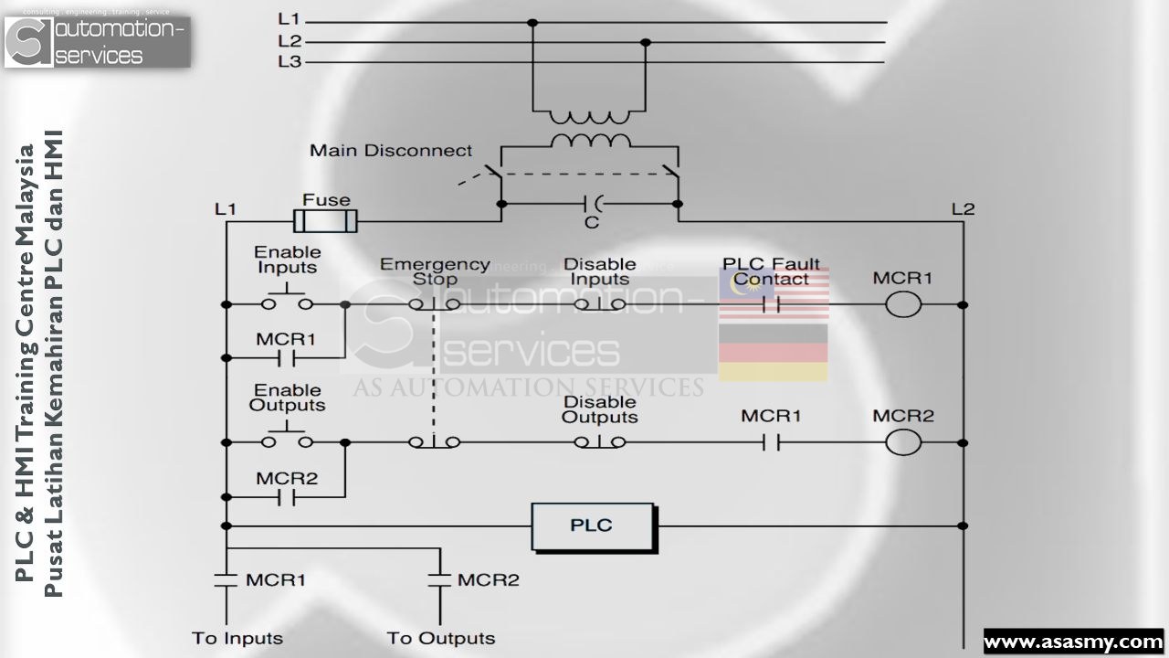
Figure 4 – Circuit that enables/disables I/O power through MCRs and PLC fault contact detection
Reference Credit :
https://electrical-engineering-portal.com/plc-power-supply-safety-circuits
https://electrical-engineering-portal.com/author/edvard
boikon.com
In AS Automation Services , we provide detailed , fully equipped with PLC hardware , software & laptop for cheapest price possible and we also provide one-to-one training
For more info contact Mr.TSoon or Whatsapp @ +60102443914
PLC Training Centre Malaysia 2020
Hashtag : #powersupply #plcpowersupply #siemensplc #omronplc #mitsubishielectric #mitsubishiplc #rockwellautomation #allenbradley #programmablelogiccontrollers #humanmachineinterface #plccontrolpanel #controlpanel #industrialautomation #malaysianindustry #industry4_0 #malaysia #malaysiaautomation #plctrainingmalaysia #skilltraining #trainingprovider #psmb #fxseries #s71200 #s7300 #contrllogic #cxprogrammer #nxseries #engineers #electricalelectronics #malaysiaskills
Learn this hands-on
Turn theory into skill with our practical PLC, HMI & SCADA training courses — HRDCorp claimable for Malaysian companies.
View Training Courses